Chapter 02 – Design Administration
Revised – 2026.01.27
TABLE OF CONTENTS – CHAPTER 02 – DESIGN ADMINISTRATION
200 – DESIGN PHASES
201 – SCHEMATIC DESIGN PHASE
202 – DESIGN DEVELOPMENT PHASE
203 – CONSTRUCTION DOCUMENTS PHASE
204 – WRITTEN REPORT
205 – CONTRACT DOCUMENTS
206 – TRADEMARKS, COPYRIGHTS AND PATENTED DEVICES, MATERIALS, AND PROCESSES
207 – DESIGN SUBMITTALS
208 – SPECIFICATION MANUALS, TABLES, ESTIMATES, WRITTEN REPORTS
209 – SUBMITTAL FORMAT – PRINTED DRAWINGS
210 – ELECTRONIC SUBMITTAL REQUIREMENTS
211 – CONSTRUCTION DOCUMENTS PHASE – FINAL SUBMITTAL
212 – SUBMITTALS CONCURRENT TO FINAL CONSTRUCTION DOCUMENT SUBMITTAL
213 – IN–PROGRESS SUBMITTALS
214 – BID PACKAGE SUBMITTAL
215 – ISSUE FOR CONSTRUCTION SUBMITTALS
216 – SUPPORTING STUDIES
200 – DESIGN PHASES
200.1 – General Information and Requirements:
A. The Project Representative is responsible for determining requirements for sub–phase submittals and quantities of physical deliverables.
1. The Project Team’s Agreement identifies the required design phase submittals.
a. If not included within their Agreement, the Project Team shall contact the Project Representative.
B. The CSU Facilities Planning, Design and Construction Standards follow the industry standard Design Phases including:
1. Schematic Design Phase
2. Design Development Phase
3. Construction Documents Phase
C. The Project Team shall deliver each phase of Design Documents to the Project Representative in accordance with the Project Schedule accepted by the Project Representative.
D. Design submittals shall include all of the requirements set forth in this chapter.
E. The Project Team shall refer to their specific Agreement for contractual requirements by phase as applicable.
200.2 – Review by Colorado State University (CSU):
A. The Project Team shall schedule a meeting(s) with the Project Representative to review its design in accordance with the individual Project Schedules accepted by the Project Representative.
B. At review meeting(s), the Project Team shall present Drawings and Documents in sufficient detail to illustrate concepts, issues, problems and proposed solutions, per discipline.
1. Design Review Committee (DRC):
a. The Project Representative shall arrange meetings with the DRC through the DRC Coordinator, at traditional design milestones according to DRC review process.
b. DRC may require electronic review or formal in person presentation/review.
c. Determination at each phase shall be indicated by the DRC.
d. Participation by the Project Team is required.
2. Refer to each phase below for additional requirements for reviews.
201 – SCHEMATIC DESIGN PHASE
201.1 – General Information and Requirements:
A. The Project Team shall refer to their specific Agreement for contractual Schematic Design Phase (SD) requirements.
201.2 – Land Surveys and Geotechnical Investigations:
A. Site Survey:
1. The Project Team shall advise the Project Representative regarding the scope of land survey required for the Project.
2. If not otherwise provided by the University, the Project Team shall perform land surveys to establish accurate dimensioned location information and to establish existing and proposed facilities.
3. Refer to Chapter 08 – Surveys.
B. Soils Investigations:
1. The Project Team shall advise the Project Representative regarding the scope of geotechnical investigation required for the Project.
2. If not otherwise provided by the University, the Project Team shall conduct geotechnical investigations as required to complete the design of the Project.
3. Refer to Chapter 09 – Construction Testing and Code Compliance.
201.3 – Alternative Design and Construction
A. Based on the Preliminary Written Report reviewed and accepted by the Project Representative, prepare written descriptions, analyses and evaluations of alternative concepts or designs that the Project Team or Project Representative considers viable for all or portions of the Project.
B. Provide substantiated recommendations for the most viable alternatives.
C. Provide Cost Estimates for alternatives.
D. Refer to Chapter 07 – Construction Evaluation and Administration.
201.4 – Schematic Design Documents:
A. The Project Team shall prepare Drawings in sufficient detail to illustrate design concepts, Systems concepts, interfaces, scale and relationships.
B. The Drawings shall identify all Project(s) components, systems, circulation and access, including site plans, access and circulation floor plans, schematic space plans, building systems, emergency exiting plans, building elevations and sections with overall dimensions and mechanical/electrical/ communications design concepts.
C. Drawings shall illustrate alternate solutions and preferred options.
1. Site Plan with existing utilities shown
2. Floor Plans of all floors, with rooms identified by program name and number
3. Exterior Elevations (minimum two)
4. Building Sections
5. Preliminary one–line Drawings of HVAC systems
6. Preliminary one–line Drawings of Electrical Distribution system
7. Perspective sketch of structure
201.5 – Study Perspectives and Models:
A. The Project Team shall prepare study Drawings, including but not limited to interior and exterior perspective sketches or isometric views of the overall Project site and portions of the Project, hand–drawn sketches demonstrating the experience/character of the conceptual design and technical views of a computer–based three–dimensional building information model.
B. Include adjacent buildings, streets, walks, trees, parking and other context.
C. Pedestrian viewpoint is preferred over bird’s eye view.
D. When required by the Scope of Work, or where the Project Representative and Project Team agree that the relationship of building components is difficult to evaluate two–dimensionally, the Project Team shall prepare rough, to–scale models of the Project or portion involved.
201.6 – Utility Incentive Programs:
A. The Project Team shall participate in meetings with utility representatives arranged by the Project Representative to determine which incentive programs may be relevant to the Project.
201.7 – Final Schematic Design Review:
A. The Project Team shall follow the Design Review Process as described in 207.5.
202 – DESIGN DEVELOPMENT PHASE
202.1 – General Information and Requirements:
A. The Project Team shall refer to their specific Agreement for contractual Design Development Phase (DD) requirements.
202.2 – Contents:
A. Design Development Drawings shall be developed in sufficient detail to define the location, character, material composition, scope and size of the Project; to identify potential problem areas associated with completing the Project and to describe proposed solutions to the problems.
B. Drawings shall provide overall dimensions, code required dimensions and clearances, spot elevations and dimensions of existing and adjacent elements, and shall conform to the CSU Facilities Planning, Design and Construction Standards.
C. Drawings shall include building plans, enlarged partial plans, building sections, enlarged wall sections, exterior and interior details, reflected ceiling plans, elevations, parking plan, site plan, study perspectives and study models if required (non–returnable), showing all building spaces and relationships.
D. Drawings shall fully illustrate all constructed areas, space planning and component sizes, scope, systems, interfaces, spaces, functions, general materials and finishes.
E. The Project Team shall carry alternates equal to 20% of the Construction Budget to be deployed as the project progresses upon approval from the Project Representative.
202.3 – Civil Drawings:
A. Including but not limited to existing site grading, existing site demolition, new paving, grading, horizontal control coordinates, vertical elevations, horizontal and vertical clearances, fencing, storm Water Detention Systems and analysis, site engineered retaining walls, special structures, and utilities including site electrical (primary and secondary), site lighting, outside fiber, water, sewer, natural gas and other special Systems as required.
202.4 – Landscape Drawings:
A. Including but not limited to plants, irrigation, flatwork, site systems and site furnishings.
202.5 – Demolition Drawings:
A. Including but not limited to Demolition Documents identifying the extent of demolition required for construction to proceed, including all Systems to be removed, capped and abandoned.
202.6 – Envelope Drawings:
A. Including but not limited to the design and location of complete and functional enclosure of all building spaces.
202.7 – Structural Drawings:
A. Including but not limited to foundations plans, caissons plans, excavation details, nominal sizes, types and cross–sections of structural members and systems, critical structural clearances, interfaces, modifications to the base building structural Systems and details necessary to define the structural system.
202.8 – Systems Deliverables:
A. Including, but not limited to the following:
1. Mechanical Drawings:
a. Tentative equipment schedules tagged to plan locations for all major equipment including chillers, boilers, air handlers, pumps, tanks and separators, heat exchangers
b. Scaled plans of each floor, showing duct layouts, equipment locations, terminal devices with supply and return diffusers
c. System schematics (one–line diagrams) of all air, hydronic, and refrigerant heating and cooling systems
d. Mechanical room, roof, and site Drawings showing all major components and piping. Show elevation cross sections where necessary.
e. Tables with HVAC load and outside air calculations
f. Control System schematics showing all controlled components and devices with detailed sequences of operation
g. Roof Layout Drawing indicating intake and exhaust louvers and flue locations
h. Tables indicating vibration analysis and mitigation appropriate to the Project’s requirements
i. Utility connections to District Energy Systems where applicable
j. Meter, submeter and associated data drop and power locations
2. Plumbing and Fire Protection Drawings:
a. Tentative equipment schedules tagged to plan locations for all major equipment including water heaters, heat exchangers, storage tanks, recirculation pumps, fire pumps, sump pits, waste interceptors, backflow preventers
b. Plans of each floor, noting fixture locations and types. Indicate routing of main distribution lines with sizes.
c. System schematics (one–line diagrams) of all Piping Systems (domestic cold and hot water, industrial cold and hot water, gas, sewer, storm, specialty lab gases, and Fire Protection)
d. Location and sizes of all water, sanitary sewer, primary and overflow storm drain and sprinkler piping
e. Location of all floor drains, roof drains and floor sinks in toilet rooms, mechanical rooms etc.
f. Tentative fixture schedule. Provide a fixture–count calculation sheet.
g. Utility connections to site Piping Distribution Systems if required by the design
h. Meter, submeter and associated data drop and power locations
i. Proposed custodial closet locations and mop sink fixtures at each floor
j. Roof Layout Drawing indicating proposed roof penetrations for storm drains, roof vents, water heater flues and combustion air inlets
3. Electrical Drawings:
a. Updated narrative description of the proposed electrical system, audio visual, telecommunications, fire alarm, and security infrastructure
b. Electrical site plan showing utility transformer location, generator (if applicable), telecom service and site lighting
c. Power plans showing power and data device locations and mechanical equipment connections, if known. Identify electrical rooms with power and transformer locations.
d. Low voltage plans showing proposed MDF/IDF closet locations at each floor. Identify main fiber conduit and cable tray. Show fire alarm panel, devices and security card readers and cameras
e. Lighting plans showing tentative lighting fixture layout, exit and emergency lighting. Initial lighting control matrix indicating typical room control scheme (ie. office, classroom, hallway, stairwell)
f. Progress equipment schedules for any mechanical, kitchen or laboratory loads. Identify what loads, if any are redundant or non–simultaneous (ie. lead lag).
g. One line diagram indicating proposed power distribution equipment
h. Progress NEC load calculations
i. Meter, submeter and associated data drop and power locations
202.9 – Alternatives:
A. Analyses of alternative building components and systems.
1. The analyses shall include comparisons of construction and life cycle costs, and operational and maintenance advantages and disadvantages.
202.10 – Signage:
A. Plans and elevations of exterior and interior building signage, graphics and selective demolition.
202.11 – Interface Drawings:
A. Showing System and facility interfaces with related and adjacent Projects.
202.12 – Standard Drawings:
A. Standard Drawings, including but not limited to, those furnished by the University, the Project Representative, or the Project Team.
202.13 – Art Program:
A. Plans for incorporating the University’s Art Program into the Project where applicable.
1. Consideration must be given to exterior utilities and landscape, electrical including lighting and power, structural systems, fire alarm and suppression systems, finishes and security.
2. Consult the Project Representative regarding scope of art installation as applicable.
3. Refer to https://www.fm.colostate.edu/upac for more details.
202.14 – Preliminary Specifications:
A. The Project Team shall prepare a complete set of Specifications for each Project in the Construction Specifications Institute (CSI) MasterFormat 2018.
202.15 – Final Design Development Review:
A. The Project Team shall schedule a final review of its Design Development Documents with the Project Representative and present the Documents described in the CSU Facilities Planning, Design and Construction Standards to the Project Representative at this meeting.
1. Design Development Drawings
2. Outline Specifications
3. Design Development Written Report
4. Design Development Cost Estimate
5. Construction Schedule
6. Lists of Acceptances, Equipment and Long–Lead Items
7. Construction Agreement Bid Documents Packaging
8. Value Engineering Report
B. After this submittal has been delivered and presented at the Final Review meeting, the Project Representative shall then have a minimum 14 calendar days to provide the Project Team with written comments, instructions and information requirements.
C. In the event the submittal is not accepted, the Project Representative shall include specific reasons for the rejection and the Project Team shall commit to a date for resubmitting the Design Development Documents after the necessary corrections or changes have been incorporated.
D. If the rejection resulted in part from the Project Team’s failure to comply with the terms of this Contract, the Project Team shall, at no cost to the University, provide its plan for recovering any time lost caused by the rejection.
E. During this review period, the Project Team shall continue with any of the work required by this Agreement unless it is notified specifically to the contrary by the Project Representative in writing.
203 – CONSTRUCTION DOCUMENTS PHASE
203.1 – General Information and Requirements:
A. The Project Team shall refer to their specific Agreement for contractual Construction Documents (CD) requirements.
B. Based upon Design Development Documents reviewed and accepted by the Project Representative and University, and the incorporation of any changes or adjustments directed by CSU, the Project Team shall prepare complete Construction Documents and shall also provide the following:
1. Final Written Report (if applicable per Agreement)
2. Agency and Utilities Applications for Permits
3. Geotechnical Study (if not provided by CSU)
4. Exterior and interior building signage schedules
C. Construction Documents shall be complete in all respects, providing sufficient information for bidding and construction, without reliance on extensive pre–bid site inspection.
1. Refer to Project–specific Agreement for details.
D. The Project Team shall review procurement documents provided by the Project Representative and incorporate them into the final Construction Document submittal as applicable.
E. Construction Documents submitted for final code compliance review shall be signed and sealed by the Designer(s) of Record.
F. The Construction Documents shall designate base bid and bid alternates, as coordinated with the Project Representative.
203.2 – Construction Documents Phase 30%/60%/90% Submittals:
A. Refer to Project–specific Agreement. The “%” does not mean 30%/60%/90% of the Drawing.
1. Prior to start of design, Project Team shall provide Construction Document submittal schedule to the Project Representative for approval.
a. For example, each Drawing required for the Construction Document package shall be 30%/60%/90% complete, including but not limited to title block, backgrounds annotations, object placements, annotations, key note development, key plan development, schedules if approved by Project Representative, etc.
2. This submittal is a step beyond the typical “cartoon” or “mock–up” of a package.
204 – WRITTEN REPORT
204.1 – General Information and Requirements:
A. The Project Team shall develop and maintain a Written Report for the Project. Refer to Project–specific Agreement for applicability.
1. At conclusion of the Bidding Phase as applicable, the Project Team shall provide revision sheets to update the previously submitted report with changes made as a result of final review, amendments and Addenda during advertising or bidding.
2. In cases of extensive Addenda and changes, the Project Representative may require resubmittal of the entire Written Report as a conformed document.
B. Submittal of the Written Reports shall follow the following requirements:
1. Each submission/update of the Written Report shall provide sufficient detail to present a clear, complete and concise picture of the design of the facilities and systems.
a. Drawings and Specifications delivered without an updated and current Written Report may not be accepted.
2. Submittals shall be submitted via the Design Review process.
a. Contact Project Representative for guidelines regarding the Design Review process.
3. The Project Team shall maintain and update the Written Report on a continuous and on–going basis to serve as a record suitable for evaluation of design process and progress not only at milestones, but at any time during the Project.
4. At the beginning of design, the Project Team shall prepare a Preliminary Written Report addressing all of the items noted below to the extent known following the pre–design meetings at the beginning of the Project.
5. Confer with the Project Representative to set the schedule for submittal and level of completion expected for each item.
204.2 – Contents:
A. The Written Report should contain the following sections:
1. Title Page
2. Table of Contents
3. Participants:
a. List Project participants, including Project Team, Project Representative, etc.
4. Certification of Compliance with the CSU Facilities Planning, Design and Construction Standards
a. Written certification that all deliverables under this Agreement conform to the Standards
b. Identify any elements that the Project Team recommends variance from the Standards.
c. Include a formal request for variance. Refer to Chapter 01 – General Project Information.
5. Program Statement:
a. Summarize the needs and analysis of the Project.
b. Include program conclusions, recommendations, ideas and strategies to accommodate the needs.
6. Diagrams:
a. Logic programs, decision matrices, associative diagrams, functional diagrams, etc.
7. Interviews and Meetings:
a. Meeting minutes of all interviews and meetings
i. Minutes shall be reviewed by the Project Representative prior to incorporation into the Project files.
8. Description of Services:
a. Describe engineering services such as geotechnical surface and subsurface investigations, vibrations analyses, acoustical studies, lighting studies, seismic analyses, line–of–sight studies, vehicular and pedestrian traffic studies, surveys and other technical studies required to design the Project.
9. Limits of Project Team Work:
a. After consultation with the Project Representative, describe agreed–upon limits of each member of the Project Team’s Scope of Work.
b. Describe any work by other Project Teams in areas adjacent to, affected by or interfacing with the Project Team’s Work.
10. Project Limits:
a. Define the limits of construction and any interface with other Projects.
i. Include records of correspondence involving coordination with other Project Teams, utility agencies and code agencies.
b. Provide a Project layout including site plan, improvements, and general sections identifying the scope of the Project and limits of work. Include approximate area calculations.
11. Design and Construction Schedule:
a. Provide design schedule and construction schedules for the Project in a format accepted by the Project Representative.
b. Refer to Chapter 07 – Construction Evaluation and Administration.
12. Summary of Actions:
a. Provide a summary of the required actions, acceptances, permits or additional information from Facilities Management, user groups, University, governmental entities and private entities which the Project Team shall require to complete its Scope of Work.
13. Budget and Funding:
a. Summarize the overall Project Budget.
14. Bid Documents:
a. Project Team recommendations for construction bid package approach for the project as applicable per the Project Team Agreement(s).
b. The Project Representative may require the Project Team to prepare separate bid packages to achieve the anticipated Project Delivery Budget and Schedule.
204.3 – Design Requirements:
A. The Written Report shall include a written discussion of design solutions, phasing, materials, risk assessment, compatibility with building Systems, all building Systems, design interfaces, equipment, performance criteria, maintenance considerations, operational compatibility, alternatives, construction scheduling, Cost Estimates, construction operation, special conditions and other construction issues.
B. The Project Team shall present factors considered and provided in the design of the Project and its components, with supporting justification, i.e., design calculations, Cost Estimates and other data.
204.4 – General Narrative:
A. Describe facilities and Systems designed by the Project Team in relation to user needs, codes, standards and other functional criteria.
B. Major Project criteria, including funding sources and budget
C. Interpretation of the major Project Criteria
D. Site plan selection factors, including utility availability and capacity
E. Spaces, areas, adjacencies and other relationship requirements
F. Existing components, Systems and/or furnishings, with capacities and required modifications
G. Exterior materials
H. Structural Systems
I. Mechanical Systems
J. Electrical Systems
K. Energy and resource conservation strategies
L. Area summary (gross, net assignable and maintenance/custodial space)
M. Cost of construction and economic factors, initial and life cycle costs influencing design choices
N. Schedule
204.5 – Design Criteria:
A. List general criteria pertaining to all disciplines used in the design, including prescribed criteria, specific studies and minutes of pre–design conference meetings.
B. Specific criteria used by each particular discipline shall be completely documented in the text of that discipline.
204.6 – Sustainable Design Strategies:
A. List and describe sustainable design strategies to conserve resources and protect the environment. Compare benefits and costs to incorporate or eliminate each strategy, and discuss alternatives.
B. Prepare USGBC – LEED scorecard for the Project. For Projects seeking LEED certification, report status of USGBC process.
C. Refer to Chapter 04 – Drawing and Document Administration.
204.7 – Major Components:
A. List major components of the Project and interfaces with larger Systems of the University, City of Fort Collins, utility companies and other entities.
204.8 – Code Analysis:
A. Complete code analysis of the Project including occupancy types and impacts on adjacent uses.
B. Include approach to code compliance.
C. Include Plan Drawing(s) of pedestrian exiting diagrams with contributory loads of various occupied areas, paths of egress with load factor, vertical egress paths with load factors, and opening/corridor size factors.
204.9 – Life Safety, Security, and Communications Systems:
A. Identify all Life Safety, Security Systems, and Communications Systems with relationship to existing Systems and capacity requirements.
204.10 – System Load Requirements:
A. Identify design load requirements by listing all of the Systems associated with a Project and their proposed calculated demand and contributing loading requirements.
1. Including, but not be limited to grey water, domestic water, stormwater (surface and piped), dirty water, fire suppression water, sewage conveyance, heating, cooling, ventilation, electrical power, natural gas, communications, dedicated information technology power and cooling, fire alarm, access control, security, lightning protection, cathodic protection, roadways, parking, exit corridors, etc.
2. The support data and calculations for this summary shall be located in a separate section or volume of the Written Report.
204.11 – Energy Conservation Requirements:
A. Identify energy loads and calculation factors.
1. Discuss which energy design method is recommended for the Project and explain why it is preferred (International Energy Conservation Code, ASHRAE Energy Design Guidelines, Appendix G Cost–Based Energy Modeling, etc.)
204.12 – Utility Incentive Programs:
A. Identify applicable incentive programs including but not limited to Fort Collins Utilities, Platte River Power Authority, Xcel Energy and other resource utilities.
1. Identify contact information and program requirements and submittal schedule.
2. Identify the specific type of documentation required and related deadlines.
3. Coordinate with the Project Representative and Energy Engineering regarding utility incentive programs.
204.13 – University Master Plan:
A. Describe how the design complies with the University Master Plan, participates in shaping public space and identifying specific elements that respond to the intent of the guidelines.
204.14 – Design Alternatives:
A. Provide design alternatives with recommendations and impact on Project Budget and schedule.
B. Define alternatives for improvements to the design and allowances for future growth, expansion or upgrade.
1. Alternatives in layouts, sizes, locations, and geometry
2. Alternatives in materials, with varying sizes and properties
3. Alternatives in operation and maintenance requirements
4. Alternatives in design requirements, i.e. codes, standards and loading criteria
5. Opportunities to provide initial rough–in or substrate for future changes
6. Alternatives in sustainable design strategies
7. Cost analysis of alternatives, including life–cycle and return on investment
204.15 – Costs and Budget:
A. Provide Cost Estimates for the Project.
1. Refer to Chapter 07 – Construction Evaluation and Administration.
2. Account for discrepancies and propose design and budget alternatives to reconcile differences between cost and budget.
3. List and explain selection of cost data sources.
204.16 – Area Tabulation:
A. Indicate Net Assignable Square Feet (NASF) and Gross Square Feet (GSF) of all spaces.
B. Indicate amount by which programmed space exceeds or falls short of program.
C. Complete the Building Maintenance and Custodial Space Report.
1. Refer to Chapter 06 – Requirements by Space Type and Use.
204.17 – Value Engineering:
A. Assist the Project Representative in completing value engineering studies as required to evaluate design alternatives by comparing performance criteria with initial and operating costs, scheduling and load evaluations.
1. Value Engineering studies shall include a lifecycle cost to compare options.
204.18 – Operations and Maintenance (O&M) Criteria:
A. List design provisions that enhance and reduce the time and cost of operating and maintaining the facility when completed.
B. Describe the O&M requirements of the design.
C. Describe the inspections, monitoring, testing, maintenance and security processes.
D. Identify O&M critical activities most critical to satisfactory operations.
204.19 – List of Equipment and Long Lead Items:
A. List all long–lead time equipment, fixtures, systems, software or accessories for which procurement activity must be accelerated.
1. If long–lead procurement is planned to begin before completion of the Construction Documents, the A/E shall prepare bid package including but not limited to Drawings, Specifications, exhibits and schedules.
204.20 – Critical Construction Activities:
A. Prepare a list of critical construction and manufacturing activities that the Project Team shall observe and monitor during the Construction Administration Phase.
1. These activities shall be identified in the Construction Documents.
2. Refer to Chapter 07 – Construction Evaluation and Administration.
204.21 – Independent Testing Laboratory Report:
A. Provide a matrix indicating the type, quantity and quality of tests to be performed by an independent testing laboratory.
1. The matrix rows shall correlate to CSI MasterFormat 2018 divisions of work.
2. The matrix columns shall identify from left to right the following: CSI Division, CSI Division Title, System or material to be tested, type of test and quantity of tests.
B. The quantity of tests shall be identified as actual number of tests, not as a percentage of the work.
1. For each test, recommend whether the Special Inspector should serve as the quality assurance agent of the Project Representative or the quality control agent of the Contractor.
2. This information shall also be incorporated in the Consultant Cost Estimate.
a. Refer to Chapter 07 – Construction Evaluation and Administration.
204.22 – Contract Data Submittal Report (CDSR):
A. The Contract Data Submittal Report (CDSR) is a spreadsheet of all submittals required by the Project Specifications. This document is not part of the Bid Documents.
1. The CDSR shall be provided initially no later than the 60% Construction Document Submittal and amended for subsequent document submittals including the Issue For Construction.
2. The CDSR shall identify each submittal and acceptance required during the duration of the work from construction notice–to–proceed to final completion.
3. The Report format shall include the following in columns from left to right: Contract Specification Section Number, Paragraph Number, Submittal Description, Related Sections, Number of Copies, Format of Contractor’s submittal.
204.23 – Cut Sheets:
A. Cut Sheets shall be submitted via the Design Review process.
1. Contact Project Representative for guidelines regarding the Design Review process.
B. The cut sheets shall be for items currently available on the market during the specific design phase.
C. The Project Team shall be responsible and verify that the items specified are readily available up to the date the Construction Documents.
204.24 – Design Calculations:
A. Provide copies of all calculations from which design decisions were made. Identify design, demand and contributory loads.
1. Provide engineering load requirements, design criteria and assumptions made to determine sizes, capacities, etc. for all Systems.
B. Divide this section by design discipline.
1. Identify each page with the Project title and location.
2. Present calculations in clear and legible form with a table showing all design loads and conditions, formulas, and references.
3. Explain all assumptions, cross–references and conclusions.
C. Indicate the software and version used for design analysis by computer.
1. Include description of the analytical method, assumptions, theories, and technical formulas.
2. Source code or other proprietary information is not required.
3. Include input schematic diagrams, input data, output data in printed form and electronic file submitted digitally.
D. If a standard design or other design is being site–adapted and a Written Report exists, the analysis for the new Project shall include the material from the original analysis that was site–adapted, in addition to the revised analysis.
E. Describe all major Civil and Building Systems, including but not limited to: stormwater, traffic, mechanical, electrical, communications, structural, foundations, plumbing, life safety, fire suppression, security, fire alarm, fiber optics, communications, signage and any other required Systems.
1. Infrastructure Support Systems, Geometry, Loads, and Schedule:
a. Pedestrian and vehicle traffic patterns and volumes, emergency access, traffic controls
b. Utilities including electrical power, gas, sanitary, storm, water, graywater, communications
c. Life Safety including fire department access
d. Security including monitoring and police access
e. Egress during emergencies, egress loads contributed to other areas and Systems
2. Site and Civil Systems:
a. Landscaping area, irrigation loads and controls
b. Stormwater flow, stormwater management, floodplain impact/mitigation, snow removal/storage, erosion control, ground water quality, environmental controls
3. Building Systems:
a. Occupancy and area calculations
b. Structural load requirements by code
c. Hazard area diagrams and calculations
d. Code Analysis including Plan Drawings indicating new and existing occupancy types, occupancy numbers, exiting directions and load tabulations, egress widths and ratings of separations. This document shall be incorporated in the Drawings.
e. Soils and structural support analysis
f. Structural Systems analysis including vibration analysis
g. Mechanical Systems analysis including energy, noise and vibration analysis
h. Electrical Systems analysis including cathodic protection of utilities, heat gains, harmonics where necessary
i. Plumbing Systems analysis including roof drainage
j. Fire Suppression Systems analysis
k. Communications Systems analysis
l. Conveyance Systems
4. Provide Energy and Mechanical Systems Design Criteria Summary as follows:
a. Outside Design Conditions:
i. Summer – °F dry bulb, °F wet bulb, percent relative humidity
ii. Winter – °F dry bulb
b. Inside Design Condition for Each Zone:
i. Summer – °F dry bulb, °F wet bulb, percent relative humidity
ii. Winter – °F dry bulb
c. Supply Air Design Conditions (List both cold and hot deck conditions if applicable):
i. Summer – °F dry bulb, °F wet bulb, percent relative humidity
ii. Winter – °F dry bulb
d. Air Change Rate Special Occupancies:
i. Air Changes/Hour (ach) for outside air or mixed air
ii. Listing of areas with positive or negative pressures requirements
e. Filter Efficiency Each Occupancy:
i. Current MERV rating per ASHRAE Standards for each occupancy
f. Building Air Systems:
i. Supply Air:
a) Summer – Total Bldg cfm and cfm/sf
b) Winter – Total Bldg cfm and cfm/sf
ii. Laboratory – ach
a) Fume Hoods
b) Biosafety Hoods
c) Laminar Flow Hoods
d) Storage Cabinets
iii. Animal Rooms – ach
iv. Outside Air:
a) Minimum Ventilation – Total Bldg cfm and cfm/sf
b) Minimum Ventilation – cfm/Person
v. Economy Cycle – cfm
vi. Exhaust Air:
a) Minimum General – Total Bldg cfm
b) Toilet – Total Bldg cfm and ach
c) Economy Cycle – Total Bldg cfm
d) Fume Hoods – cfm per hood and Face Velocity at 12” Sash Height
e) Total Number of hoods and Total Number of fans
vii. Special Systems – Stack heights, filters, design requirements
g. Control Description: Each of the following Systems should have a sequence of operation description and a discussion of direct digital versus other Control System.
i. Air Systems
ii. Supply air (including hood make–up air)
iii. Return air
iv. Exhaust air
v. Room Control or Building Pressure
vi. Steam and Condensate
vii. Hydronic Heating and Cooling
viii. Domestic and Industrial Hot Water
ix. Compressed Air
x. Special (compressed gases, glycol, brine, etc.)
xi. Process Heating and Cooling
h. Flow Rates or Demand at Design Conditions:
i. Steam – lb/H
ii. Gas – cf/H
iii. Electricity – KW
iv. Chilled Water – gpm and tons, temperature supply/return
v. Hot Water Heat – gpm and Btuh, temperature supply/return
5. Each calculation shall include a list of the basic criteria, including design assumptions, current Office of the State Architect (OSA) adopted editions of applicable codes, standards and references.
a. List sources for major equations and computer programs.
b. Show the source of formula, equation, input data or assumption and derivation of all uncommon calculations.
c. The applicability of existing solutions to new problems shall be explained in writing before they are adopted.
6. Calculations shall be orderly and complete with enough sketches and notes so that the work can be understood.
a. Diagrams indicating data (such as loads, flows, voltages and dimensions) shall be included along with adequate details for nonstandard conditions.
204.25 – Calculation Quality Control:
A. Maintain a calculation quality control program that includes checking by a design professional whose qualifications are sufficient to originate the calculation. The checker shall not be the originator of the calculations.
B. Check calculations against the Design Drawing to verify whether they conform to specified configurations, dimensions, and materials.
C. Check calculations for assumptions, analytical methods, mathematical accuracy, completeness, compliance with design criteria, and the adequacy of design.
D. Initial and date each page of the original calculations after they are completely checked and all necessary corrections have been made. Attach initialed alternate calculations, if used.
E. When checking computer calculations, the checker shall check:
1. Project–specific programming for assumptions, program theory, compliance with the flow diagram and overall correctness.
2. Applicability of standard programs and the assumptions made for setting up the calculation.
3. All input data for correctness, as well as the application of output data.
204.26 – Revisions:
A. All parts of the calculation that are dependent on the revision shall be checked. Review the complete original calculation to determine which parts are dependent.
B. It is not necessary to recheck parts that are independent of the revision. Results of calculation revisions shall be distributed to all parties affected by the change.
C. Maintain records of original calculations that were revised by crossing them out and marking “SUPERSEDED” on the page.
1. Prepare new calculation sheets for all superseding calculations, except for minor changes where the designer may authorize a cross–out, initials the change and identifies it with a revision number on the calculation cover sheet.
2. Original calculations shall be kept in each discipline’s section of the Project calculation file in the Written Report.
3. Calculations shall be separated into groups: Preliminary, Final and Superseded and provided with an index.
D. The Project Team shall review all design calculations prepared by his group for technical adequacy and conformance with design requirements.
1. Preliminary calculations shall be reviewed and initialed by the responsible designer and clearly marked “PRELIMINARY”.
2. Final calculations, including computer calculations, shall carry the stamp, seal, and signature of the respective Consultant.
3. The Project Team is liable for the constructability and the function of the System designed.
204.27 – Appendix:
A. Provide each appendix with a title page and table of contents (index) and number pages consecutively for each appendix. Explain all assumptions, cross–references and conclusions.
1. Cost Estimates
2. Outline Specifications
3. Data reports
4. Product data
5. Conference minutes and correspondence relative to the design and referenced in other sections
205 – CONTRACT DOCUMENTS
205.1 – General Information and Requirements:
A. Contact Project Representative for University–specific sample Agreements.
B. The Project Representative develops Project–specific Agreements on a per–Project basis.
C. Refer to Project–specific Agreement and Procurement Documents.
205.2 – Special Conditions:
A. Special Conditions shall be given precedence over General Conditions.
B. The Special Conditions are modifications of the General Conditions of the Contract; the terms are written by University Legal Services with input from the Project Representative and the Project Team.
205.3 – Supplementary General Conditions (SGC):
A. Supplementary General Conditions are established by CSU and shall be given precedence over General Conditions.
B. SGC typically address insurance requirements.
205.4 – General Conditions of Contract (GCC):
A. Established by the State of Colorado.
B. General Conditions shall be given precedence over Specifications except when the Specifications set a higher standard or more stringent requirement than the General Conditions; then the Specifications shall be given precedence.
C. The Project Team shall review and be familiar with the General Conditions and assure coordination of Subconsultant Work with the GCC.
1. Optional Provisions and Elections at the end of the GCC modify preceding Articles regarding:
a. Guarantee Inspections
b. Federal Wage Rates
c. Non–Binding Dispute Resolution
d. Liquidated Damages
D. Specifications shall be given precedence over Construction Drawings.
1. The Project Team shall not repeat Specifications in annotation of the Drawings.
2. This condition does not relieve the Project Team from showing complete elevations and sections of specified products on the Drawings with full dimensional coordination.
3. If alternate products are specified, the alternate shall be illustrated on the Drawings with a notation.
4. Larger scale Drawings shall be given precedence over smaller scale Drawings.
a. This requirement does not relieve the Project Team from liability for accurate coordination of dimensions between small–and large–scale Drawings.
5. In the event of conflict or inconsistency between provisions of the Specifications, the more stringent shall be given precedence over the less stringent.
a. This requirement does not relieve the Project Team from liability for coordination of all aspects of the Specifications, including Specification Division 01 – General Requirements.
6. The CSU Facilities Planning, Design and Construction Standards shall not be referenced in the Construction Documents.
a. The Project Team shall be responsible for complete coordination of the Specifications with the requirements of the Standards.
b. Refer to Chapter 04 – Drawing and Documents Administration.
206 – TRADEMARKS, COPYRIGHTS AND PATENTED DEVICES, MATERIALS, AND PROCESSES
206.1 – General Information and Requirements:
A. The Project Team may not publish as part of the Bid Documents copies of designs, Shop Drawings, or materials by Contractors, designers, or suppliers without written authorization from that Project Team, designer, or supplier.
B. Refer to Project–specific Agreement for royalties and patents.
207 – DESIGN SUBMITTALS
207.1 – General Information and Requirements:
A. The Project Team shall provide Design Submittals that include information the Project Representative requires to monitor the Project Team’s progress and compliance with the Agreement and the CSU Facilities Planning, Design and Construction Standards.
1. Design Submittals may include but are not limited to Design and Construction Documents, Specifications, Cost Estimates, Phasing Plans, Schedules, Alternate Lists, Allowance Schedules, Bid Package Descriptions, etc.
207.2 – Design Submittal Review and Approval:
A. Each required Design Submittal shall be complete and in compliance with the Agreement and the CSU Facilities Planning, Design and Construction Standards.
1. Design Submittals shall be reviewed by the Project Team prior to submittal to the Project Representative.
2. Review by CSU shall not be construed as replacing the Project Team’s Quality Control Program.
3. Review and comments by CSU do not relieve the Project Team from liabilities of providing complete design services and are not an acceptance of any errors or omissions that may be contained in the documents.
4. Review of a separate item shall not constitute review of an assembly in which the item functions.
a. The Project Representative shall withhold acceptance of submittals which depend on other submittals not yet submitted.
b. Review and acceptance shall not relieve Project Team from their responsibility for accuracy of submittals, for conformity of submittal documents to requirements of Construction Drawings and Specifications, for compatibility of described product with contiguous products and the rest of the system, or for protection and completion of the Project in accordance with the Construction Drawings and Specifications.
5. The Project Team is responsible for the interdisciplinary coordination and communication within their team with whom their work may interface.
B. The Project Representative shall reject any Design Submittals that do not adequately represent the required level of completion, do not include all relevant design disciplines, systems, project requirements or do not include all the required documents.
C. Partial or incomplete submittals shall be accepted by the Project Representative for review purposes only when the Project Representative requires them for a specific purpose or has otherwise authorized their submittal.
1. Partial submittals to the Project Representative shall not relieve the Project Team of its commitments to meet Schedule and Budget requirements contained in the Agreement.
207.3 – Design Submittal Review Schedule:
A. Review timeframes shall be consistent with the Project Schedule, per the Agreement.
B. CSU shall have fourteen calendar days after delivery to the Project Representative to complete a review and submit comments unless otherwise agreed upon.
C. The Project Representative shall provide the Project Team with their comments, requirements, approved tenant comments and specific instructions on data or information that they require be incorporated into the RFP, Contract Documents or other deliverables.
D. In the event the Design Submittal is not accepted, the Project Representative shall include specific reasons for the rejection and the Project Team shall commit to a date for re–submittal after the necessary corrections, instructions or changes have been incorporated.
E. If the rejection resulted in part from the Project Team’s failure to comply with the terms of the Agreement, the Project Team shall also provide at no cost to CSU its plan for recovering any time lost caused by the rejection.
F. During this review period, the Project Team shall continue with any other work required by the Agreement unless it is notified specifically to the contrary by the Project Representative in writing.
207.4 – Certification:
A. The A/E shall certify in writing that all of the RFP or Contract Documents are in conformance with the CSU Facilities Planning, Design and Construction Standards and all code agency requirements and that the documents are complete.
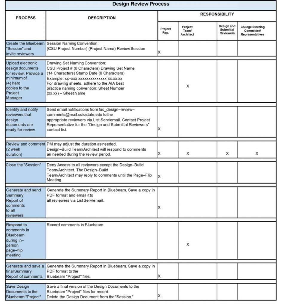
207.5 – CSU Design Review Process:
A. The Project Team shall follow the Design Review Process as described in the table below.
207.6 – Project Team Response to CSU Review:
A. After CSU has completed its review of a Design Submittal, the Project Team shall provide a written reply which states the Project Team’s disposition, resolution or action to be taken on each of the comments, instructions or recommendations.
B. The Project Team shall submit its reply to the Project Representative within seven calendar days after it receives CSU’s comments unless a different period of time is specifically provided in the Agreement.
C. The Project Team is solely responsible for completion and coordination of Work by Subconsultants.
1. Any deviation shall be noted and accompanied by a copy of the written authorization of deviation by the Project Representative.
207.7 – Project Team Design Quality Control Program:
A. Shall be in place to maintain a level of quality in the work product that is consistent with the Project requirements and the CSU Facilities Planning, Design and Construction Standards.
207.8 – Licensing Stamp and Signature:
A. Licensing stamp and signature shall be required on all Drawing sheets and title page of the Specifications for:
1. Submittals to Government Agencies
2. Construction Documents submitted for final Code Compliance Review
3. Construction Documents Issued for Construction
4. Record Documents
207.9 – CSU Facilities Planning, Design and Construction Standards Monitoring:
A. The Project Team shall monitor and review all of the documents for design integrity and compliance to the appropriate Standards criteria, codes and national standards.
208 – SPECIFICATION MANUALS, TABLES, ESTIMATES, WRITTEN REPORTS
208.1 – Format:
A. Specification Manuals, Tables, Estimates, and Written Reports shall follow the uniform format established in these standards and shall be submitted electronically in searchable Portable Document Format (PDF) document form unless otherwise specified in the Agreement.
B.Electronic submittals must be labeled clearly with the Project Number and Name, design phase, and date.
C. The files shall not be protected.
D. Files shall include all text, illustrations, tables, schedules and exhibits contained in the document.
208.2 – Product Data and Cut Sheets:
A. The Project Team shall provide sufficient data to verify compliance with the CSU Facilities Planning, Design and Construction Standards within the Specification Manual.
B. Product data and cut sheets shall identify System or item performance criteria, size, weight, and color as applicable.
C. If color and/or material selection is requested of the Project Representative during the design phase, original Manufacturer samples shall be provided for approval.
209 – SUBMITTAL FORMAT – PRINTED DRAWINGS
209.1 – General Information and Requirements:
A. Drawings shall be submitted in the format and size as required by the Project Representative or per the Agreement.
210 – ELECTRONIC SUBMITTAL REQUIREMENTS
210.1 – Submittal Media:
A. Submit electronic files per Project–specific Agreement or coordinate with Project Representative.
210.2 – Labeling of Media:
A. Project Teams must label all electronic media with the following information: Project Team Name, CSU Project Number, CSU Project Name, Building Name, Submittal Date, Submittal Level, and contact phone number.
B. Additionally, a hardcopy file list on 8.5″ X 11″ paper must accompany the electronic storage media when submitted.
211 – CONSTRUCTION DOCUMENTS PHASE – FINAL SUBMITTAL
211.1 – General Information and Requirements:
A. This submittal shall include all of the requirements set forth in section 205.
211.2 – Review by CSU – Final Review Meeting:
A. The Project Team shall schedule a meeting to review these documents with the Project Representative.
B. This meeting must be scheduled no later than 30 calendar days prior to the date shown in the Master Schedule for completing these documents for each Project.
211.3 – Documents:
A. Comply with requirements of the CSU Facilities Planning, Design and Construction Standards.
B. All Construction Documents shall comply with Project Agreement.
C. All design, drafting, coordination, dimensioning and cross references shall be complete and all code agency plan comments shall be resolved.
1. The Project Representative’s comments from all previous reviews must be incorporated into the Documents or otherwise addressed to the satisfaction of the Project Representative and University.
D. The Drawings shall be signed and stamped for this submittal. The quantity of original signature sets shall be determined by the Project Agreement.
211.4 – Specifications:
A. Comply with Chapter 04 – Drawing and Document Administration requirements including the submittal of the Data and Product Submittal.
B. The Specifications shall be in final draft format and shall be submitted per the Project Agreement.
C. The Project Representative’s comments from all previous reviews must be incorporated into the Specifications or otherwise addressed to the satisfaction of the Project Representative and University.
211.5 – Final Bid Document Package:
A. The documentation shall identify base bid, alternates, unit prices and applicable allowances and be submitted in a form acceptable to the Project Representative to allow the Project Representative to review and verify the Project Team’s estimated unit prices.
212 – SUBMITTALS CONCURRENT TO FINAL CONSTRUCTION DOCUMENT SUBMITTAL
212.1 – Agency and Utilities, Applications and Permits:
A. Identify all design or construction related governmental permits, licenses or other acceptances which are required to complete each Project.
B. Prepare and submit to the Project Representative technical data and information required to prepare any grant or permit application from any University, State and Federal agency, regulatory body, department or public utility.
1. These submittals shall include the number of copies of Construction Drawings and Specifications the agency may require in connection with its review and acceptance of the application. The Project Representative shall submit these applications to the appropriate agency, utility and/or department.
C. The Project Team shall prepare submittals to the government department, agency, regulatory body and/or public utility any technical data, following the Change Order process within the Project Agreement, which agencies require to issue any new or modified permits or acceptances, and shall provide the quantity of copies required by the Project Representative for the application.
D. Incorporate all revisions necessary to obtain the governmental permits, licenses or other acceptances into the Construction Documents.
E. Document all discussions relating to permits, licenses and acceptances with University, State and Federal agencies, regulatory bodies, departments and with public utilities.
1. Within three business days of meetings or discussions, provide the Project Representative with copies of all meeting minutes and all serialized correspondence sent to and received from such agencies, departments, and public utilities relating to permits or acceptances, including copies of the relevant application for permit, license and/or acceptance.
213 – IN–PROGRESS SUBMITTALS
213.1 – General Information and Requirements:
A. The Project Representative may require in–progress submittals at any time during the term of the Project Agreement.
1. These submittals may be required to address specific questions or issues related to matters such as interface problems or other issues identified by the Project Representative or the University.
B. The Project Representative shall provide the Project Team with its requirements for in–progress submittals with reasonable advance notice to allow the Project Team to schedule and prepare the submittal.
214 – BID PACKAGE SUBMITTAL
214.1 – Bid Package Submittal:
A. Upon completion of the Final Review Submittal and the Project Representative’s written acceptance of this submittal, the Project Team shall complete the Construction Documents.
1. Refer to Project–specific Agreement for requirements. The Project Team shall provide an electronic edition of the Construction Documents.
B. The Contract Documents shall be completed, reviewed, checked, signed and sealed by the Project Team.
1. The Project Representative’s comments, the University’s comments and approved reviewer comments from previous reviews shall be incorporated in the Construction Documents and all outstanding issues shall be resolved to the satisfaction of the Project Representative and University.
C. The Project Team shall then, no later than seven calendar days prior to when Advertisement for Bids (AFB) or RFP is advertised, deliver the finalized Construction Documents to the Project Representative for final conformance review and acceptance.
D. The Drawing sheets and Project Manual shall each be minimized to as few PDFs as possible.
1. At a minimum, Drawings shall be an individual PDF and Specifications shall be an individual PDF.
215 – ISSUE FOR CONSTRUCTION SUBMITTALS
215.1 – General Information and Requirements:
A. The Project Team shall incorporate all Addenda issued by the Project Representative during the procurement process into the Construction Documents as directed by the Project Representative.
216 – SUPPORTING STUDIES
216.1 – General Information and Requirements:
A. At the request of the Project Representative, the Project Team may be requested (under a separate authorization) to provide additional focused planning studies and/or analysis directly related to the Project beyond those normally required for the design process and related coordination.
B. The purposes for these supporting studies may include documentation for grants, additional justification, design refinement, etc.
END OF CHAPTER